Shapes in Docusnap are graphical images of elements. These are needed, for example, to visually represent the structure of a rack. Examples for shapes are servers, workstations, power strips, UPS, patch panels, etc.
Shape Editor
Docusnap supplies ready-made shapes. The existing shape collection can be extended using the Shape Editor.
For newly created other assets, a corresponding shape is automatically created.
Use Shape Editor
The Shape Editor is started within the Infrastructure Editor via the  button and the selection Edit Element Types.
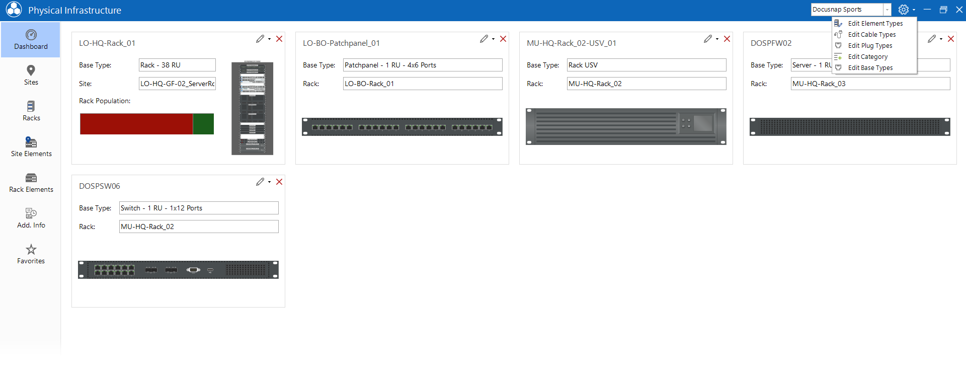
New - Element (Shape Editor) can now be selected in the newly opened Manage Shapes window.
Working with the Shape Editor
Adding new shapes
In order to be able to create new shapes, corresponding image files are required first. Please note that front and back side are required.
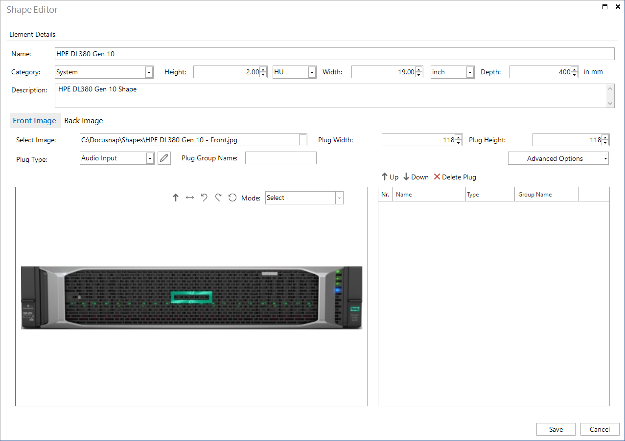
In the first step information regarding name, type, height, width and depth are entered. The values refer to the actual size of the object.
The image files are then made available. Image files can be made available to the Shape Editor already cut. However, the Shape Editor also has an integrated Crop mode.
Define Plugs
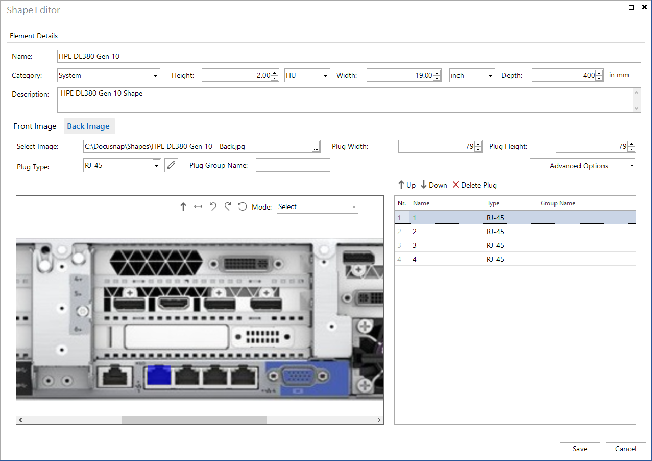
Docusnap automatically recognizes the possible plug connections of the shape. The following figure shows the detected plugs (marked red).
|
By adjusting the plug width and height, the algorithm is able to detect plug connections that were not detected during the first run. |

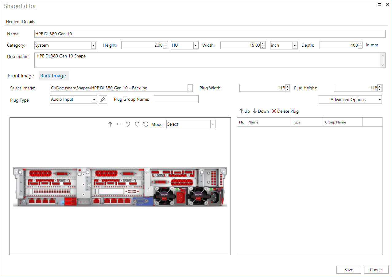
A connector is defined by selecting the plug type on the shape. By clicking on the red area representing the connector, it is added to the list as a plug. Before a selection is made, the appropriate plug type should be selected so that it does not have to be adjusted manually afterwards.
Add Undetected Plugs
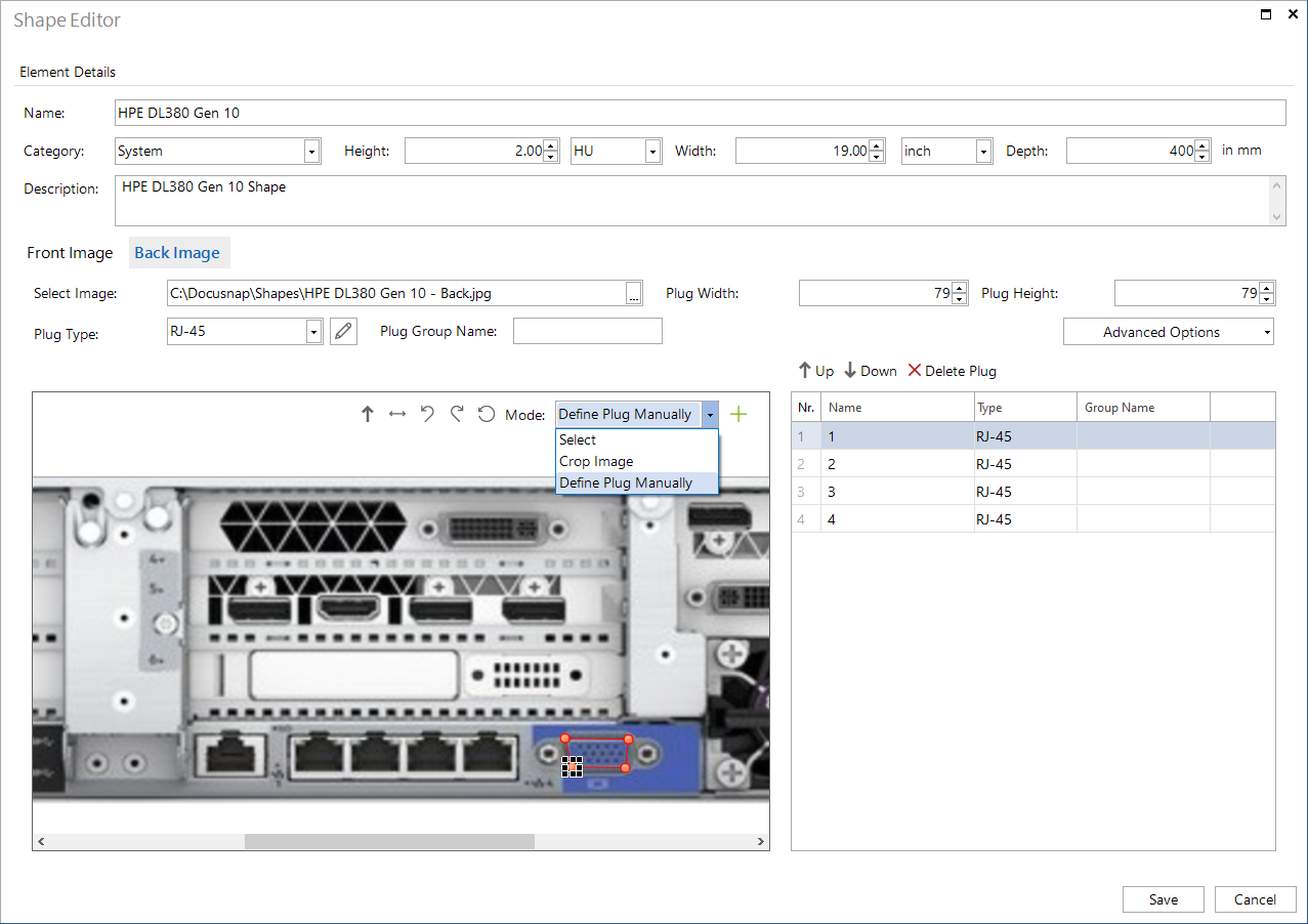
If individual plugs are not detected automatically, they can be added manually. The Define Plug Manually mode is used for this purpose.
The position of the plug can be defined with the aid of four marking points.
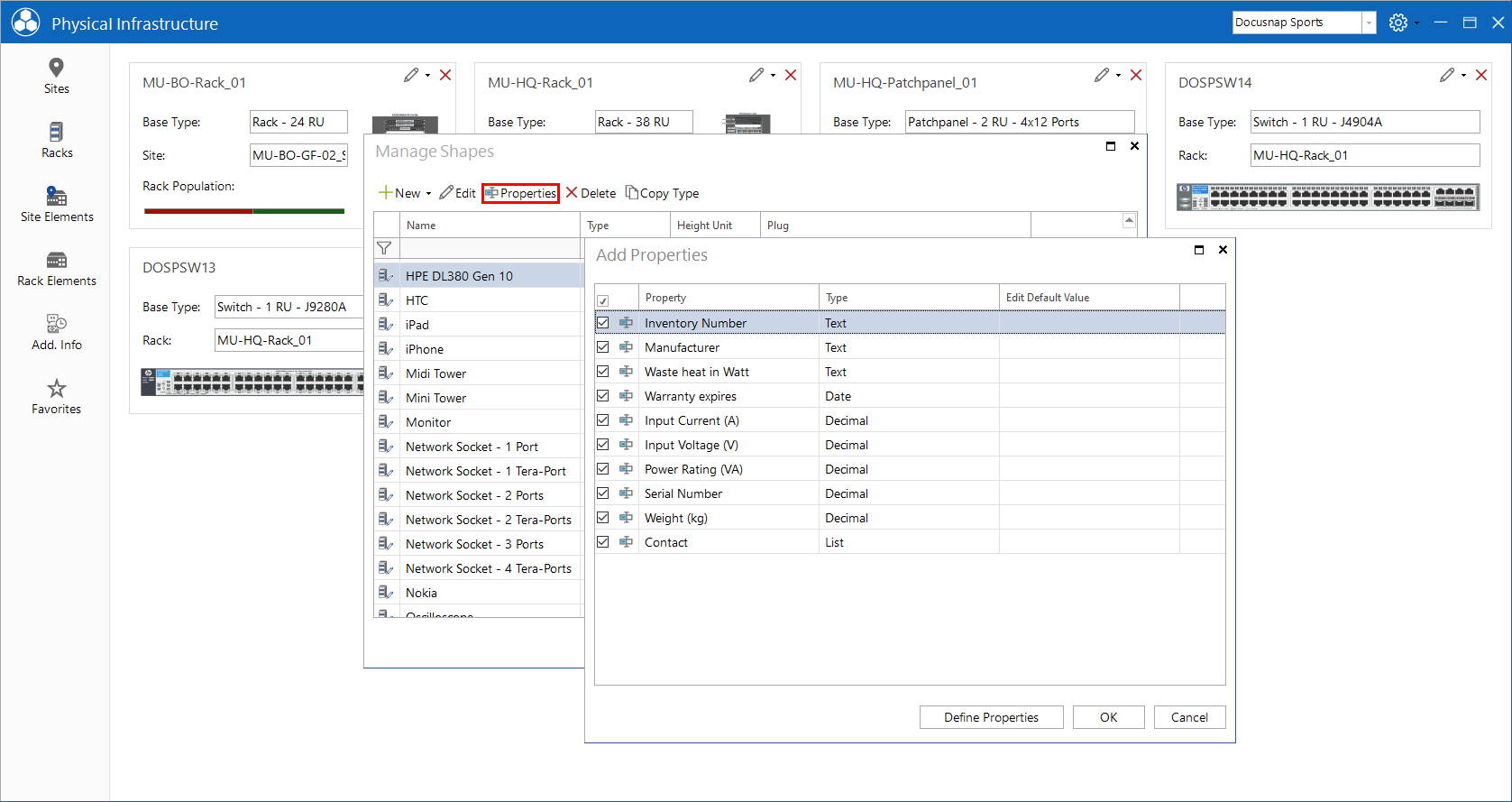
Add Properties
Further properties (e.g. weight, current consumption etc.) can be added to an element via and the Edit Element Types option.
To assign properties to an element, it must be selected. The Properties button opens an overview of the available properties.
The Define Properties button can be used to create additional properties and assign them to the element.